Cable Installation
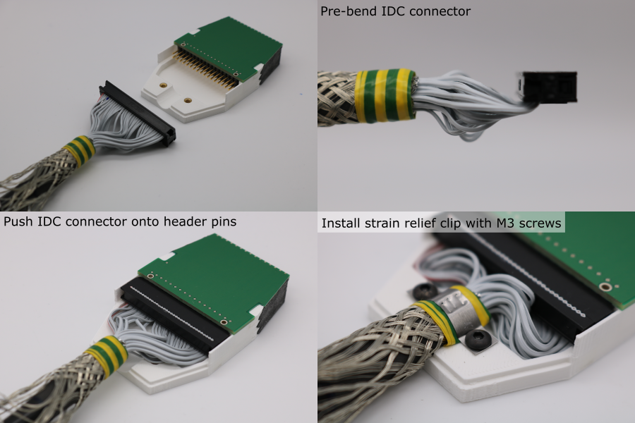
Installation
- Identify the transducer end of the cable.
- Pre-bend the IDC connector so that the sockets are coaxial with the cable.
- Hold the cable so that the polarity indicators (embossed triangle / red wire) are on the left.
- Push the IDC connector onto the PCB header pins.
- Secure the cable to the transducer housing using the strain rleief clip and M3 x 5 mm socket head screws. Make sure the clip grips the sheathed part of the cable, and not the individual wires.
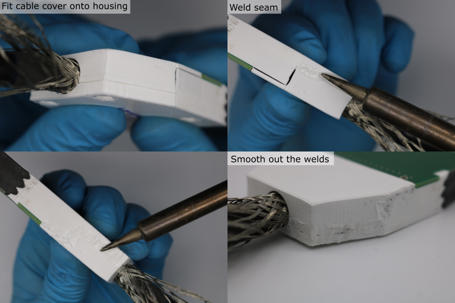
Cable Cover Welding
- 3D-print the cable cover (orientation and slicer settings detailed in 3D-print-spec.pdf).
- Setup a soldering iron with a temperature of 275 °C and a very clean tip. Setup an extraction fan.
- Hold the cover piece in place. Make sure that the copper braid is not caught in the cover-housing seam.
- Tack weld the cover-housing seam using the soldering iron.
- Fully weld the cover-housing seam, pushing the tip deep into the seam to achieve good penetration.
- Smooth out the welded seam using the soldering iron tip.